This is Paul Wade W1GHZ's 222 Transverter, that appears in the January 2003 QST.
First, some links:
Here are some photos and light discussion.
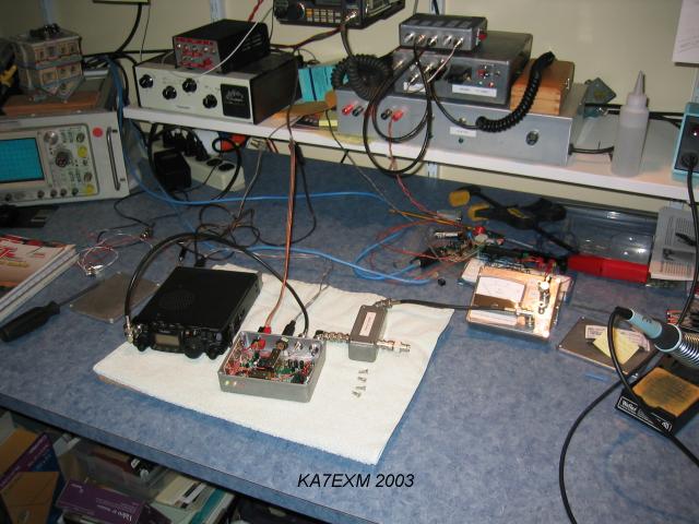
Here it is...FT-817, Transverter, and the power meter for output power measurement. Note that numerous power measurements were taken on-board (soldering coax in place) during construction. You're looking at "the whole shack" there. FT-290Rii for local SSB chatter, DSP-10 for future weak signal experiments. FT-817 for everything else. DVM, W7ZOI Power Meter, Frequency Counter, and a Tek 465 O'scope (via eBay) and that's all there is. Blue wires are Cat-5 / RJ-45 lines back to the computers on the other side of the office.
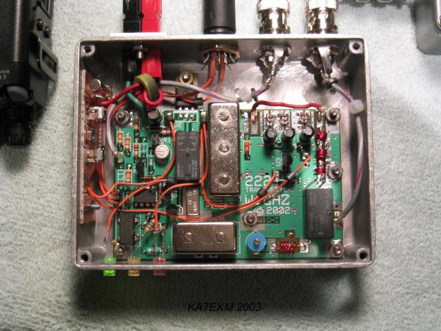
A closeup of the transverter. No major variations to Paul's layout.
Note the missing Mitsubishi Hybrid. The RF line has been bridged across during testing. I can still run +10dBm output without it. That is plenty for alignment / spectral analysis, etc. Note a torroid on the power line in the upper left. On the left wall of the box is a 2A fuse, along with an additional spare fuse clipped on (near the top). Each of the wires from the DIN connectors received heat-shrink tubing prior to installation in the cabinet. NOTE: The din-din patch cable has heat-shrink cable over the active pins. In addition, I would suggest covering the +13.8V DC pin on BOTH ENDS of the cable with a piece of heat shrink. This helps minimize the possibility that the cable will ever apply a power-ground short through the rig. Note also that the FT-817's 13.8V ouput pin through the accessory jack CAN NOT supply current for outboard transverters. (An SMT part inside the 817 will fuse open if you try. Fortunately I found out about this the easy way).
Power comes in via Anderson Power Pole connectors in the upper left. I have some neat mounting brackets that allow for chassis-mounted connections. These power connectors are fantastic.
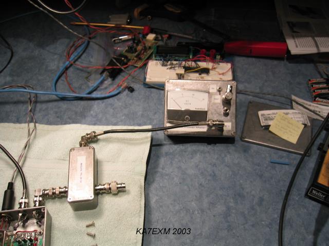
Here is a closeup of the apparatus used for power measurements. My apologies for the cruddy shot. Hey, it was early. The W7ZOI / W7PUA power meter is used to measure power. More accurate measurements are taken by using the DVM output, or the LCD display & code on the PIC processor board behind the meter (but that's another project). The 40dB tap is terminated with a BNC dummy load. The measurements to the meter are 40dB lower than actual levels (because +10dBm is just a tad more than what you want to stuff into the meter). The power meter is in the June 2001 QST, and really should be considered a must-have for the bench.
Feel free to send constructive feedback. Keep experimenting!
ka7exm at gmail dot com